EI-OT ESP-01+ ESP8266 RS232 Module Jumper Setting  |
Jumper setzen
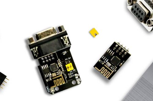
Nach entsprechender Bestückung verfügt das Modul über eine DB9 (female) Anschlussbuchse. Dementsprechend sind die Pins des DB9 Anschluss wie folgt belegt:
Dementsprechend müssen die RS232 Signale zu 3232 Level Shifter IC mittels Jumper gemäß nebenstehender Grafik gesetzt werden. An dieser Stelle sei erwähnt (leider ein sehr häufiger Fehler) der einfache Wechsel durch Kreuzen der Pin’s auf einen DB Stecker funktioniert nicht! Im Detail wird hierzu der Pin4 des DB9 benötigt, dieser ist nicht belegt. Rein theoretisch könnte man aber einen DB9 Male Anschluss auf der Unterseite der Platine platzieren. |
Jumper setting
After appropriate assembly, the module has a DB9 (female) connection socket. Accordingly, the pins of the DB9 connection are assigned as follows:
Accordingly, the RS232 signals must be set to the 3232 level shifter IC using jumpers according to the graphic. At this point it should be mentioned (unfortunately a very common mistake) simply switching to a DB connector by crossing the pins does not work! In detail, pin 4 of DB9 is required for this; it is not assigned. In theory, you could place a DB9 male connection on the underside of the board. |
EI-OT dual RS232 Module connection  |
Spannungsversorgung
Die zentrale Spannungsversorgung erfolgt über die Pins
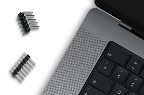
Anschluss RS232 – 2
Der zweite RS232 Anschluss erfolgt über die 7-polige Pinleiste
der RS232 Schnittstelle |
Power Supply
The central voltage supply is provided by
Power Supply
The second RS232 interface is provided by Pin Header
to RS232 Interface |
EI-OT dual RS232 Module attach ESP-01+ ESP8266 Module  |
ESP-01+ Modul aufstecken
Nachdem die benötigten Anschlüsse hergestellt wurden, muß lediglich das ESP-01+ Modul auf den Stecksockel aufgesteckt werden. |
attach ESP-01+ Module
After the required connections have been made, the ESP-01+ module simply needs to be plugged into the socket. |