EI-OT PCB 8 Channel PRO Relays Module 7.5-26V MP1584 Power Supply |
Relais Modul 7,5-26V Spannungsversorgung
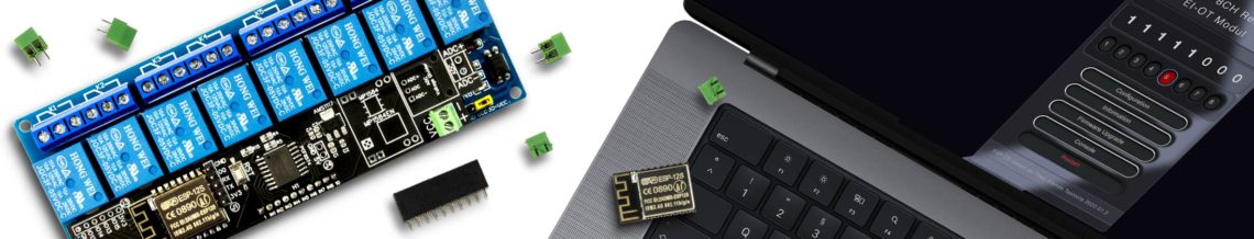
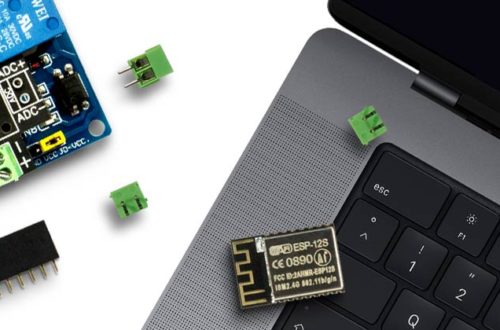
Um das EI-OT 8 Kanal Relais mit höheren Spannungen (größer 5V) zu betreiben, muss die Steuerungsplatine zusätzlich mit einem MP1584EN 5V Spannungskonverter erweitert werden. Die EI-OT 8 Kanal Relais PRO Platine ist bereits vorbereitet und erlaub eine einfache Bestückung des MP1584EN Spannungskonverter. Wichtig, bei der Platzierung des MP1584EN muss auf die richtige Positionierung geachtet werden
gemäß Darstellung auf der Platine. Die Bestückung des Spannungskonverters Schritt für Schritt:
Die Spannungsversorgung über den MP1584 Konverter ist fertiggestellt. Der MP1584 konvertiert Eingangsspannungen von 7,5V bis 26V auf 5V. Die Spannungsversorgung erfolgt zentral (auch für das 5V 8 Kanal Relais Modul / blaue Platine) über die 2-polige KF350 Schraubklemme. |
Relays Module 7.5-26V Power Supply
In case of EI-OT 8 Chanel PRO Relays Module is operated with power supply between 7.5V and 26V a MP1584EN Voltage Converter is required. The 8 Channel Relays PRO Module its prepared for easy assembling of the MP1584EN. Important, please take care of correct orientation of the MP1584 Module, in detail
just follow MP1584 figure on PCB. MP1584EN Voltage Converter Module assembling step by step:
The 8 Channel Relays Module PRO supports now central power supply from 7.5V up to 26V thru 2-pole Screw Connector. |
5V Standard Relays Module Power Supply  |
Relais Spannungsversorgung
Die 5V Spannungsversorgung des EI-OT 8 Kanal PRO Relais erfolgt zentral durch die Steuerungsplatine. Da aber 5V Relais Module sich in der Spannungsversorgung unterscheiden können, muss die Versorgungsspannung der Relais auf der Unterseite der EI-OT 8 Kanal Relais Platine entsprechend gebrückt werden. Es sind 2 Versionen von 5V 8 Kanal Relais Modulen verfügbar Version1: Hier muss auf der Unterseite der EI-OT 8 Kanal Standard Relais Platine Version2: Hier muss auf der Unterseite der EI-OT 8 Kanal Standard Relais Platine Die Spannungsversorgung des 5V 8 Kanal Relais Moduls ist fertiggestellt. |
Relays Power Supply
The Power Supply of the Relays is supported thru the controller PCB. The power supply of 5V Standard Relays Module could be different. In this regard the Relais Voltage Supply must be connected on backside of EI-OT 8 Channel Module PCB. There are 2 types of 5V 8 Channel Standard Relays Module available Version1: please connect 5V > 1 Pads Version2: please connect GND > 1 Pads The Power Supply of the 5V 8 Channel Relays Module is finished. |
Assembling EI-OT PCB and Standard 8 Channel PRO Relays Module |
Relais Modul verbinden
Sobald die Platine fertig bestückt wurde und die , können Steuerungsplatine und das 8 Kanal PRO Relais Modul zusammengesetzt werden.
Das EI-OT 8 Kanal PRO Relais ist nun einsatzbereit. |
Relays Module Connection
Soon as the PCB is assembled, the controller PCB and the Relays Module can be assembled.
The EI-OT 8 Channel PRO Relays Module is finished. |
EI-OT 8 Channel PRO Relays Module 5V power supply  |
Spannungsversorgung
Die Spannungsversorgung erfolgt mittels KF350 Schraubklemme, Anschluss
Als Netzteil eignen sich typische
Die Spannungsquelle sollte mindestens 750mA bereitstellen um ausreichende Leistung für die Relaisspulen bereitzustellen. |
Power Supply
Connect Power Supply thru KF350 Screw Connector
Typical Power Supplies are
The minimum Current should be 750mA. |