PC817 Optokoppler am 8 Kanal ESP8266 Smart Home Relais anschliessen  |
Optokoppler Anschluß
Oftmals steht man vor der Aufgabe andere / höhere Signalspannungen im Bereich von 5 bis 24V auf die 3,3V (GPIO) Spannung eines ESP8266 umzusetzen. Ganz gleich ob
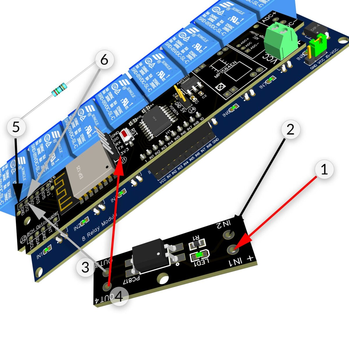
mittels einem PC817 Optokoppler kann die jeweilige Spannung, galvansich getrennt (es gibt keinen elektrischen Leiter zwischen Eingangsspannung und Ausgangsspannung) auf 3,3 Volt reduziert werden. Anschluss eines PC817 Optokoppler Moduls mit einem Pull Down Widerstand
Erläuterung
Wird der IN (+IN1 und -IN2) des PC817 Optokoppler Moduls geschaltet, wird die 3,3V Spannung von OUT4 auf OUT3 geschaltet und dementsprechend 3,3V auf den ESP8266 GPIO geschaltet. Beim Öffnen des PC817 Modul Eingang (keine Signalspannung) fließt weder + noch – auf den GPIO. Da aber der GPIO auch mit dem Pull Down Widerstand verbunden ist, fliesst – / GND über den Widerstand auf den GPIO. Der GPIO erhält somit ein LOW Level Signal. |
Optocoupler Connecting
Often a Voltage Conversion between Signal Voltage, for example 5V to 24V to ESP8266 3.3V GPIO Level is required. The external Signal can be a
in combination with a PC817 Module the external Signal Voltage is (galvanic isolated) converted to required ESP8266 3.3V GPIO Level. Connecting a PC817 Optocoupler Module to an ESP8266
Description
Soon as the Optocoupler is in active state – gets a Signal Voltage – OUT4 is connected to OUT3 and the ESP8266 gets 3.3V+. In case of PC817 is inactive / no Signal Voltage, there is no 3.3V+ nor – / GND is send to GPIO. Because of GPIO is connected to Pull Down Resistor, the GPIO gets a – and has a LOW Level. |