
EI-OT ESP8266 2 Kanal Relais Modul Bestückung und Anschluss
- EI-OT 2Kanal Relais Modulbausatz bestücken
- EI-OT 2 Kanal Relais Platine anschliessen und mit 2 Kanal Relais Modul verbinden
Bestückung und Zusammenbau des ESP8266 EI-OT 2 Kanal Relais Modulbausatz
ESP8266 2 Channel Relays Module assembling  |
Zusammenbau / Bestückung
Das EI-OT ESP8266 2 Kanal Relais Modul ist bereits mit SMD Komponenten bestückt. Zur Inbetriebnahme müssen nachfolgende Komponenten wie in nebenstehender Grafik (zum Vergrößern auf das Bild klicken) bestückt / verlötet werden Die Bestückung des EI-OT 2 Kanal Relais Modul Schritt für Schritt:
Das EI-OT ESP8266 2 Kanal Relais Modul ist fertig bestückt, sodass im nächsten Schritt die notwendige Verbindung zum Betrieb des 5V 4 Kanal Relais Modul hergestellt werden kann. |
Assembling
Besides the SMD components, the EI-OT ESP8266 2 Channel Standard Relays Module requires additional components. Assembling of the EI-OT 2 Channel Relays Module Step by Step:
The basic assembling of the EI-OT ESP8266 2 Channel Standard Relays Module is finished. |
Assembling ESP8266 2 Channel Relays Module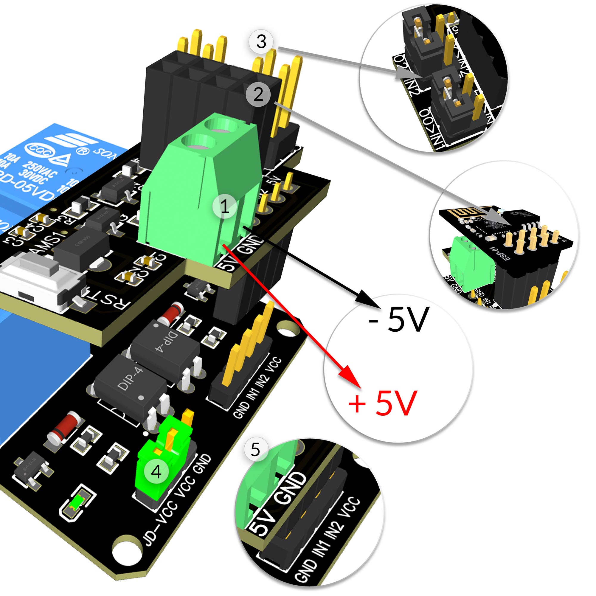 |
Relais Modul verbinden
Sobald die Platine fertig bestückt wurde, können Steuerungsplatine und das 2 Kanal Relais Modul angeschlossen und zusammengesetzt werden.
Das EI-OT ESP8266 2 Kanal Standard Relais ist nun einsatzbereit. |
Relays Module Connection
Soon as the PCB is assembled, the controller PCB and the Relays Module can be connected to power supply and assembled.
The EI-OT ESP8266 2 Channel Standard Relays Module is finished. |
Letzter Beitrag: Source code ESP-OS zur fehlerfreien Compilierung Unser neuestes Mitglied: Harald Becker Neueste Beiträge Ungelesene Beiträge
