Tasmota ESP-12 5V 4 Kanal Sensor Relais Bausatz

11,90 €

EI-OT ESP8266 ESP-12 Tasmota 4 Kanal Tasmota Sensor Relais Modulbausatz zum Schalten und Steuern über WLan Netzwerken

Beschreibung

Tasmota ESP8266 ESP-12 4 Kanal Sensor Relais Bausatz

ähnliche Produkte
related items
Spannungsversorgung
Power Supply
Sensoren
Sensors
Zubehör
Accessoires

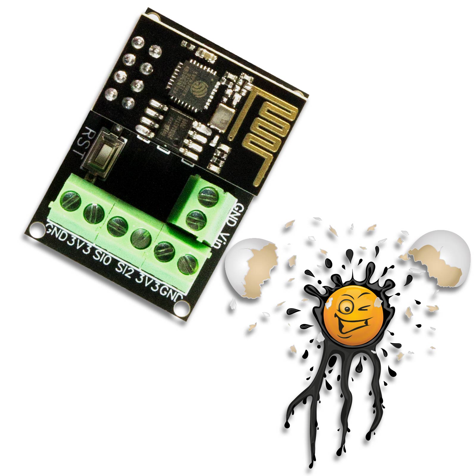
Das ESP8266 4 Kanal Sensor Relais Modul ist erlaubt den Betrieb von 4 Relais in Kombination mit 2 digitalen Eingängen und 1-Wire oder I2C Sensoren.

Das EI-OT ESP8266 4 Kanal Tasmota Sensor Relais Modul basiert auf dem ESP8266 ESP-12S mit integrierter  2dBi Antenne. Der ESP8266 ESP-12 verfügt über einen 32Mbit SPI Flash Speicher und erlaubt eine einfache Integration in Heimnetzwerke mittels Tasmota.

Tasmota Firmware

Der ESP8266 ist bereits mit einer passenden Tasmota Firmware ausgestattet und bietet einen weitreichenden Funktionsumfang. Grundlage bilden dabei die 4 Ausgänge / Relais die mittels Tasmota Konfiguration und Kommandos in Kombination mit 1-Wire oder I2C Sensoren (nicht im Lieferumfang enthalten) wie beispielsweise DS18B20 betrieben werden können. Ferner können 2 optoisolierte (5 bis 24V), digitale Eingänge in den Funktionsumfang eingebunden werden. Die Firmware unterstützt sämtliche Tasmota Kommandos welche individuell mittels Tasmota Rules automatisiert werden können.


Ausgänge 4 Relais

Die 4 Relais des EI-OT ESP8266 4 Kanal Sensor Relais Board werden über

  • GPIO13 = Relais 1
  • GPIO12 = Relais 2
  • GPIO14 = Relais 3
  • GPIO16 = Relais 4 (bitte beachten schliesst bei der Spannungsversorgung für ca. 1 Sekunde)


Eingänge 2 5-24V optoisoliert

Des Weiteren verfügt das 4 Kanal Sensor Controller Board über 2  optoisolierte, digitale Eingänge an

  • GPIO5 = IN1 Klemme 5 bis 24V
  • GPIO4 = IN2 Klemme 5 bis 24V

für Benutzereingaben mittels Taster, Schalter, Reed Kontakt, Sensor mit digitalem Ausgang, usw. Die übliche Konfiguration über das Tasmota Webinterface erfolgt hier beispielsweise als Button, Schalter, Counter, ….


Sensoren 1-Wire I2C

Das 4 Kanal Sensor Relais verfügt über zahlreiche 1-Wire und I2C Treiber die über die Tasmota Firmware bereitgestellt werden. Im Detail wird die 1-Wire bzw. I2C Schnittstelle über

  • GPIO0 = S0 Klemme
  • GPIO2 = S2 Klemme

bereitgestellt. Die in der Tasmota Firmware integrierten Treiber werden weiter unten aufgelistet.


Die Ei-OT ESP8266 4 Kanal Steuerungsplatine ist passend für typische 5V 4 Kanal Relais Module und wird einfach über die 6-polige Pinleiste des Relais Moduls verbunden / aufgesteckt. Dabei bedarf es keiner gesonderten Spannungsversorgung, die Spannungsversorgung erfolgt zentral über die 2-polige Anschlussklemme der EI-OT ESP8266 4 Kanal Relais Modul Platine.

Die Hauptplatine

des EI-OT 4 Kanal Sensor Relais Modul Bausatz verfügt bereits über grundlegende SMD Komponenten wie

  • 1 Stück AMS1117 3,3V Spannungskonverter sowie
  • LTV208 2 Kanal Optokoppler
  • 2 Stück SMD LED
  • 6 Stück Kondensatoren zur Glättung der Versorgungspannung
  • 4 Stück N Kanal Transistoren
  • 18 Stück SMD Widerstände
  • Reset Taster


Bausatz Lieferumfang

Neben der Hauptplatine sind im EI-OT 4 Kanal Sensor Relais Modul Bausatz folgende Komponenten enthalten:

  • 1 Stück 5V 4 Kanal Relais Modul 
  • 1 Stück Stecksockel 6-polig 1-reihig zum Aufstecken auf eine 5V 4 Kanal Relais Platine
  • 1 Stück ESP-8266 ESP-12 bereits mit Tasmota Firmware geflasht und somit betriebsfertig
  • 1 Stück Pinleiste 1-reihig 6-polig (3,3V, TXD,RXD,GND, IO0,IO2)
  • 2 Stück Schraubklemmen KF350 2-polig zum Anschluss
    • Signaleingang 1-Wire / I2C Sensoren
    • optosilierte, digitale Eingänge
  • 1 Stück Schraubklemme zur Spannungsversorgung des EI-OT 4 Kanal Relais Moduls


Das 4 Kanal Sensor Relais Modul wird mit Tasmota Firmware geliefert. Die 4 Relais können dabei direkt über das integrierte Template aktiviert werden


Die Tasmota Firmware des EI-OT ESP8266 4 Kanal Thermostat Relais hat Treiber für folgende Sensoren und Module bereits integriert

1-Wire Sensoren und Module:

    • DS18B20 Temperatursensor
    • DHT11 zur Bestimmung von Temperatur,  Luftfeuchtigkeit, sowie Taupunkt
    • AM2301 / DHT22 auch zur Bestimmung von Temperatur,  Luftfeuchtigkeit, sowie Taupunkt jedoch mit einer höheren Genauigkeit


I2C Sensoren und Module:

    • PCF8574 I/O Erweiterung
    • BH1750 Lichtsensor zur Bestimmung von Helligkeit
    • TSL2561 Lichtsensor / Luxmeter
    • AM2320 Temperatur und Luftfeuchte Sensor
    • SHT30 Sensor zur Bestimmung von Temperatur,  Luftfeuchtigkeit
    • HTU-21 Sensor zur Bestimmung von Temperatur,  Luftfeuchtigkeit
    • BMP (BMP085/BMP180/BMP280/BME280) zur Bestimmung des Luftdrucks als auch Temperatur und Luftfeuchtigkeit (je nach Sensor)
    • BME680 zur Messung von Luftqualität CO2 TVOC
    • SGP30 Umweltsensor zur Bestimmung von CO2 TVOC
    • SGP40 Umweltsensor zur Bestimmung von CO2 TVOC
    • SGP4X Umweltsensor zur Bestimmung von CO2 TVOC
    • SEN5X Umweltsensoren
    • SGP40 Umweltsensor zur Bestimmung von CO2 TVOC
    • SI1145 UV Sensor
    • MPR121 Touch Sensor
    • CCS811 Kohlendioxid Sensor
    • ENS160 Kohlendioxid Sensor
    • MAX44009 Lichtsensor
    • SCD30 Kohlendioxid Sensor
    • SCD40 Kohlendioxid Sensor
    • SPS30 Partikel Sensor
    • MLX90614 Kohlendioxid Sensor
    • PAJ7620 Kohlendioxid Sensor
    • HIH6 Temperatur und Luftfeuchte Sensor
    • DS1624 Temperatursensor
    • HDC1080 Temperatur und Luftfeuchte Sensor
    • HIH6 Temperatur und Luftfeuchte Sensor
    • VEML6075 UVA/UVB/UVINDEX Sensor
    • VEML7700 Umgebungslicht Sensor
    • HIH6 Temperatur und Luftfeuchte Sensor
    • VL53L0X ToF Sensor zur Distanzmessung
    • LM75AD Sensor zur Temperaturmessung
    • GY-521 MPU-6050 MEMS DMP 3 Achsen Gyroskop
    • AHT10 AHT15 AHT20 Sensor zur Bestimmung von Temperatur,  Luftfeuchtigkeit
    • DHT12 Sensor zur Bestimmung von Temperatur,  Luftfeuchtigkeit
    • MCP9808 Temperatur Sensor Modul
    • ADS1115 4 Kanal ADC Konverter


The ESP8266 4-channel sensor relay module supports 4 Relays in combination with 2 digital Inputs and 1-Wire or I2C Sensors.

The EI-OT ESP8266 4-channel Tasmota sensor relay module is based on the ESP8266 ESP-12S, which features an integrated 2dBi antenna. The ESP8266 ESP-12 includes 32Mbit of SPI flash memory and allows for easy integration into home networks via Tasmota.


Tasmota Firmware

The ESP8266 comes pre-installed with compatible Tasmota firmware and offers an extensive range of features. At its core are 4 outputs/relays, which can be operated via Tasmota configuration and commands—optionally in combination with 1-Wire or I2C sensors (not included), such as the DS18B20. Furthermore, 2 optoisolated (5 to 24V) digital inputs can be integrated into the system. The firmware supports all standard Tasmota commands, which can be automated individually using Tasmota Rules.


Outputs 4 Relays

The 4 Relays of theEI-OT ESP8266 4 Channel Sensor Relays Board controlled thru

  • GPIO13 = Relays 1
  • GPIO12 = Relays 2
  • GPIO14 = Relays 3
  • GPIO16 = Relays 4 (NOTE: GPIO16 always turn on during power connection for < 1 second)


Inputs 2 5-24V optoisolated

Furthermore, the 4-channel Sensor controller board features 2 optoisolated digital inputs operated thru

  • GPIO5 = IN1 Terminal 5 bis 24V
  • GPIO4 = IN2 Terminal 5 bis 24V

for user inputs via push-buttons, switches, reed contacts, sensors with a digital output, etc. In the Tasmota web interface, these are typically configured as buttons, switches, or counters, ….


Sensors 1-Wire I2C

The 4-channel sensor relay features numerous 1-Wire and I2C drivers provided via the Tasmota firmware. The 1-Wire and I2C interfaces are accessed via

  • GPIO0 = S0 Terminal
  • GPIO2 = S2 Terminal

and configured thru Tasmota Webinterface.


The EI-OT ESP8266 4-channel control board is designed for standard 5V 4-channel relay modules and can be easily connected—or plugged directly—onto the relay module’s 6-pin header. No separate power supply is required; power is provided centrally via the 2-pin terminal block on the EI-OT ESP8266 4-channel relay module board.

Main Controller Board


The EI-OT 4-channel sensor relay module kit already includes basic SMD components, such as:

  • 1 x AMS1117 3.3V voltage regulator
  • LTV208 2-channel optocoupler
  • 2 x SMD LEDs
  • 6 x capacitors for smoothing the supply voltage
  • 4 x N-channel transistors
  • 18 x SMD resistors
  • Reset button


Bausatz Lieferumfang

Neben der Hauptplatine sind im EI-OT 4 Kanal Thermostat Relais Modul Bausatz folgende Komponenten enthalten:

  • 1 Stück 5V 4 Kanal Relais Modul 
  • 1 Stück Stecksockel 6-polig 1-reihig zum Aufstecken auf eine 5V 4 Kanal Relais Platine
  • 1 Stück ESP-8266 ESP-12 bereits mit Tasmota Firmware geflasht und somit betriebsfertig
  • 1 Stück Pinleiste 1-reihig 6-polig (3,3V, TXD,RXD,GND, IO0,IO2)
  • 2 Stück Schraubklemmen KF350 2-polig zum Anschluss
    • Signaleingang 1-Wire / I2C Sensoren
    • optosilierte, digitale Eingänge
  • 1 Stück Schraubklemme zur Spannungsversorgung des EI-OT 4 Kanal Relais Moduls


The 4-channel sensor relay module comes with the Tasmota thermostat firmware. The 4 relays can be activated directly via the integrated template


The Tasmota Firmware of the EI-OT 4 Channel Thermostat Sensor Relays Module comes with drivers for Sensors and Modules follows

1-Wire Sensors and Modules:

    • DS18B20 Temperature Sensor
    • DHT11 Temperature and  Humidity Sensor
    • AM2301 / DHT22 Temperature and  Humidity Sensor


I2C Sensors und Modules:

    • PCF8574 supports all I2C Addresses of the PFC8574 (also 0X20 and 0X38)
    • BH1750 Light Sensor
    • TSL2561 Lichtsensor / Luxmeter
    • AM2320 Temperature and  Humidity Sensor
    • SHT30 Temperature and  Humidity Sensor
    • HTU-21 Temperature and  Humidity Sensor
    • BMP (BMP085/BMP180/BMP280/BME280) Pressure and/or Temperature and  Humidity Sensor (based on type of Sensor)
    • BME680 Air Quality CO2 TVOC
    • SGP30 Air Quality CO2 TVOC
    • SGP40 Air Quality CO2 TVOC
    • SGP4X Air Quality CO2 TVOC
    • SEN5X Air Quality CO2 TVOC
    • SGP40 Air Quality CO2 TVOC
    • SI1145 UV Sensor
    • MPR121 Touch Sensor
    • CCS811 Air Quality CO2 Sensor
    • ENS160 CO2 Sensor
    • MAX44009 Light Sensor
    • SCD30 CO2 Sensor
    • SCD40 CO2 Sensor
    • SPS30 Particel Sensor
    • MLX90614 CO2 Sensor
    • PAJ7620 CO2 Sensor
    • HIH6 Temperature and Humidty Sensor
    • DS1624 Temperature sensor
    • HDC1080 Temperature and Humidty Sensor
    • HIH6 Temperature and Humidty Sensor
    • VEML6075 UVA/UVB/UVINDEX Sensor
    • VEML7700 Ambient Light sensor
    • HIH6 Temperatur und Luftfeuchte Sensor
    • VL53L0X ToF Time of Flight Distance Sensor
    • LM75AD Temperature  Sensor
    • GY-521 MPU-6050 MEMS DMP 3 Axis Gyroscope
    • AHT10 AHT15 AHT20 Temperature and  Humidity Sensor
    • DHT12 Temperature and  Humidity Sensor
    • MCP9808 Temperature Sensor Module
    • ADS1115 4 channel AD Converter


s

FAQ Häufig gestellte Fragen


EI-OT ESP8266 ESP-12 4 Channel Sensor Relays Module Features


VCC SpannungsversorgungDC 5 WICHTIGVCC  / Input VoltageDC 5 IMPORTANT
GPIO0 S0 (1-Wire / I2C) 4K7 PullUp
GPIO1 TX (frei wählbar)
GPIO2 S2 (1-Wire / I2C) 4K7 PullUp
GPIO3 RX (frei wählbar)
GPIO4 IN2 (digital 5-24V)
GPIO5 IN1 (digital 5-24V)
GPIO12 (Relais 2 )
GPIO13 (Relais 1)
GPIO14 (Relais 3)
GPIO16 (Relais 4)
GPIO0 S0 (1-Wire / I2C) 4K7 PullUp
GPIO1 TX (User selection)
GPIO2 S2 (1-Wire / I2C) 4K7 PullUp
GPIO3 RX (User selection)
GPIO4 IN2 (digital 5-24V)
GPIO5 IN1 (digital 5-24V)
GPIO12 (Relays 2 )
GPIO13 (Relays 1)
GPIO14 (Relays 3)
GPIO16 (Relays 4)

250mA (max.)

23mA (Modem Sleep)

5mA (Light Sleep)

<3mA (Deep Sleep)

250mA (max.)

23mA (Modem Sleep)

5mA (Light Sleep)

<3mA (Deep Sleep)

GPIO0 / GPIO2 with 4K7 PullUp Resistor

  1. 3V3 = 3,3V+
  2. TX GPIO1
  3. RX GPIO3
  4. GND
  5. 00 = GPIO0
  6. 02 = GPIO2

  1. 3V3 = 3,3V+
  2. TX GPIO1
  3. RX GPIO3
  4. GND
  5. 00 = GPIO0
  6. 02 = GPIO2
DS18B20, DHT11, AM2301, DHT22
PCF8574, BH1750 , TSL2561 , AM2320, SHT30, HTU-21, BMP, BMP085, BMP180, BMP280, BME280, BME680, SGP30, SGP40, SGP4X, SEN5X, SGP40, SI1145, MPR121, CCS811, ENS160, MAX44009, SCD30, SCD40, SPS30, MLX90614, PAJ7620, HIH6, DS1624, HDC1080, HIH6, VEML6075, VEML7700, HIH6, VL53L0X, LM75AD, GY-521 MPU-6050, AHT10, AHT15, AHT20, DHT12, MCP9808, ADS1115PCF8574, BH1750 , TSL2561 , AM2320, SHT30, HTU-21, BMP, BMP085, BMP180, BMP280, BME280, BME680, SGP30, SGP40, SGP4X, SEN5X, SGP40, SI1145, MPR121, CCS811, ENS160, MAX44009, SCD30, SCD40, SPS30, MLX90614, PAJ7620, HIH6, DS1624, HDC1080, HIH6, VEML6075, VEML7700, HIH6, VL53L0X, LM75AD, GY-521 MPU-6050, AHT10, AHT15, AHT20, DHT12, MCP9808, ADS1115

Zusätzliche Informationen

Sprache / Language

Deutsch, English

Tasmota

Tasmota 4 Kanal Thermostat Firmware

tasmota-4CH-Sensor-Relays.zip


enthält

tasmota-4CH-Sensor-Relays-en.bin.gz english

tasmota-4CH-Sensor-Relays-de.bin.gz deutsch

vor Verwendung ZIP Datei entpacken

Sollte ein Speicherüberlauf / Fehler beim Update auftreten zunächst auf Tasmota Minimal updaten

Setup

Tasmota 4 Channel Sensor Relays Module assembling
Zusammenbau / Bestückung

Das EI-OT ESP8266 4 Kanal Sensor Relais Modul ist bereits mit SMD Komponenten bestückt. Zur Inbetriebnahme müssen nachfolgende Komponenten wie in nebenstehender Grafik (zum Vergrößern auf das Bild klicken) bestückt / verlötet werden

Die Bestückung des EI-OT 4 Kanal Sensor Relais Modul Schritt für Schritt:

  1. Den ESP8266 (ESP12 oder ESP-07S) passend auf den PADS ggfls. mit einer Klammer fixieren auf der Platine platzieren und auf der Oberseite der Platine verlöten
  2. KF350 Schraubklemme von jeweils von oben auf der Platine platzieren und auf der Unterseite der Platine verlöten
  3. Die 6-polige Stiftleiste (optional wird nicht direkt für den Betrieb benötigt) von oben auf der Platine platzieren und auf der Unterseite der Platine verlöten
  4. Die 2-polige KF501 Schraubklemme auf der Vorderseite der Platine durchstecken und beide Pins auf der Rückseite verlöten
  5. Den 6-poligen 1-reihigen Stecksockel auf der Unterseite platzieren / durchstecken und auf der Oberseite verlöten

Das EI-OT ESP8266 4 Kanal Sensor Relais Modul ist fertig bestückt.

Assembling

Besides the SMD components, the EI-OT ESP8266 2 Channel Sensor  Relays Module requires additional components.

Assembling of the EI-OT 4 Channel  Sensor Relays Module Step by Step:

  1. Put the ESP8266 Module on PCB topside and solder all Pads on topside
  2. Put each of the  2-pole KF350 screw terminals on top of PCB and solder the 2 Pins from backside
  3. Put Pinheader on top of PCB and solder the 6 Pins from backside
  4. Put the  2-pole KF501 screw terminal on top of PCB and solder the 2 Pins from backside
  5. Put the 6-pole socket on PCB backside and solder the 6 Pins from topside

The basic assembling of the EI-OT ESP8266 4 Channel Sensor Relays Module is finished.

Tasmota 4 Channel Sensor Relais power supply connecting

Tasmota 4 Channel Sensor Relais DS18B20 Temperature Sensor connecting

Anschluss

Das EI-OT 4 Kanal Sensor Relais über 2 Anschlüsse
S0 = GPIO0
S2 = GPIO2
die jeweils über einen PullUp Widerstand verfügen und somit sowohl 1-Wire Bus, als auch I2C Bus in Verbindung mit entsprechenden Treibern unterstützen.
Das 4 Kanal Sensor Relais unterstützt bis zu 8 Stück DS18B20 Sensoren pro 1-Wire Bus.
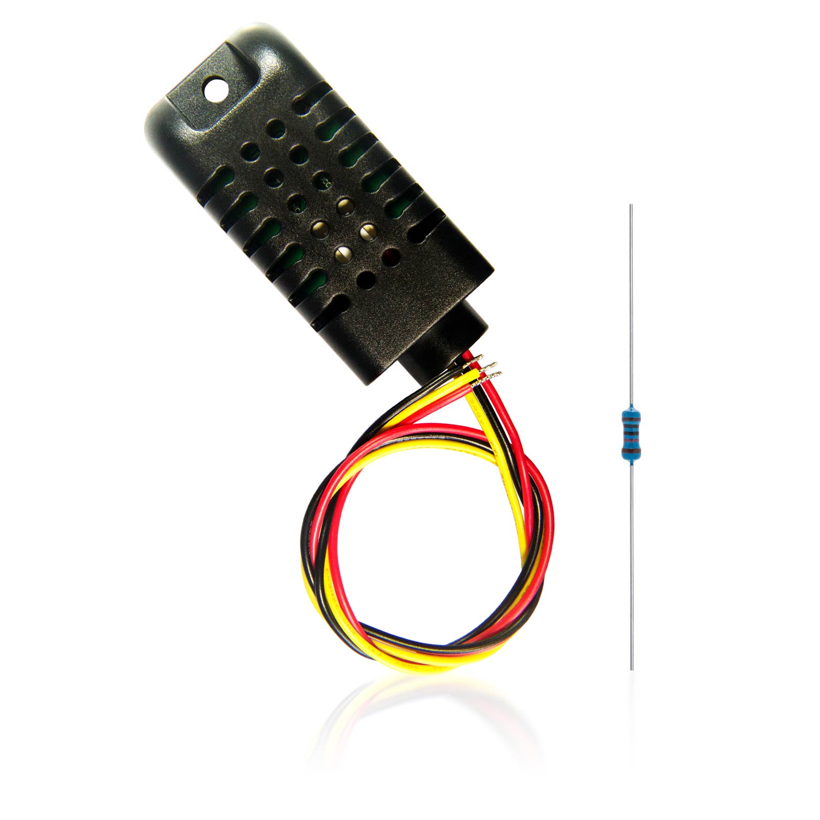
Der Anschluss eines DS18B20 Temperatursensor über die 1-Wire Schnittstelle am EI-OT 4 Kanal Sensor Relais Modul ist denkbar einfach. Der DS18B20  Sensor erlaubt Versorgungsspannungen von 3-5,5 Volt und kann somit direkt mit der 5 Volt Spannungsversorgung des EI-OT 4 Kanal Sensor Relais Moduls betrieben werden.

    1. Pin1 GND schwarz des DS18B20 wird mit GND Klemme
    2. Pin2 VCC rot des DS18B20 wird mit 5V Klemme
    3. Pin2 gelb Signal des DS18B20 Sensors wird mit der S00 (GPIO0)  Klemme oder alternativ mit der S02 (GPIO2) Klemme

verbunden.

Die Tasmota Firmware unterstützt bis zu

  1. bis zu 8 Stück DS18B20 Sensoren
  2. pro 1-Wire Bus (S00 / S02)
Connect

The EI-OT 4-channel sensor relay features two connections—S0 (GPIO0) and S2 (GPIO2)—each equipped with a pull-up resistor. This allows them to support both 1-Wire and I2C buses when used with the appropriate drivers. The 4-channel sensor relay supports up to eight DS18B20 sensors per 1-Wire bus. Connecting a DS18B20 temperature sensor to the EI-OT 4-channel sensor relay module via the 1-Wire interface is extremely straightforward. The DS18B20 sensor operates within a supply voltage range of 3–5.5 volts, meaning it can be powered directly by the 5-volt supply of the EI-OT 4-channel sensor relay module.

  1. Pin1 / DS18B20 black wire must be connected to GND Screw Connector
  2. Pin2 / DS18B20 red wire must be connected 5V Screw Terminal
  3. Pin3 / DS18B20 yellow Signal must be connected to S00 (GPIO0) or  S02 (GPIO2) Screw Terminal

The Tasmota Firmware supports up to

  1. 8 pcs. of DS18B20 each 1-Wire Bus
  2. per 1-wire Bus (S00 / S02)
Tasmota WLan WiFi Konfiguration in 5 Schritten
Tasmota WLan Konfiguration

Die Tasmota Firmware erlaubt eine einfache WLan Konfiguration mittels Webinterface. An dieser Stelle sei erwähnt, die Tasmota Firmware unterstützt den SoftAP Modus (Access Point) lediglich zur WLan Konfiguration. Sobald das jeweilige Modul als Client in einem bestehenden Netzwerk eingebunden wurde, wird der SoftAP Modus nicht mehr unterstützt.

Tasmota Client Anbindung mittels Webinterface

Nachdem das jeweilige Modul mit Spannung versorgt wurde startet das Modul im SoftAP Modus. Innerhalb der Netzwerkumgebung eines

  • Computers
  • Mobiltelefon
  • Tablet

erscheint nun ein neuer Tasmota SoftAP / Access Point.

Die WLan Konfiguration mittels dem Tasmota Webinterface erfolgt mittels 5 einfachen Schritten:

  1. Stelle eine WLan Verbindung über Systemeinstellungen / Netzwerkeinstellungen zu dem Tasmota Soft AP wird als tasmota-??????-???? Access Point angezeigt. Der Tasmota SoftAP verfügt über keine Sicherheitseinstellungen, es wird kein Passwort benötigt.
  2. Nachdem eine WLan Verbindung hergestellt wurde öffnet sich üblicherweise das Tasmota Webinterface innerhalb des festgelegten Standardbrowsers. Alternativ kann das Tasmota Webinterface durch Aufruft der url http://192.168.4.1 innerhalb eines Webbrowsers aufgerufen werden. Tasmota führt eigenständig einen Netzwerkscan aus und gibt die Liste verfügbarer Netzwerke aus. Sollte das gewünschte Netzwerk nicht im Tasmota Webinterinterface nicht aufgelistet sein, Scan for all WiFi Networks anklicken, sodass erneut ein Netzwerkscan durchgeführt wird.
  3. Wähle das jeweilige Netzwerk aus (anklicken), Tasmota übernimmt dann das jeweilige Netzwerk in das Textfeld WiFi Network. Ergänze nun die erforderlichen Parameter durch das Netzwerk Passwort und klicke auf den Button Save.
  4. Das Tasmota Modul startet eigenständig und versucht eine Verbindung mit dem zuvor festgelegtem Netzwerk herzustellen (Dauer ca. 20-30 Sekunden).
  5. Wurde die Verbindung erfolgreich hergestellt erscheint die Meldung Successful WiFi Connection sowie die Angabe der vom Router mittels DHCP zugewiesenen IP Adresse.
    1. Wichtig das Tasmota Modul ist nun nur noch über dieses IP Adresse erreichbar.
    2. Bitte WLan Verbindung überprüfen, ob sich der Client im gleichen Netzwerk wie das Tasmota Modul befindet (gegebenenfalls mit dem entsprechenden WLan Netzwerk verbinden) , da sonst kein Redirect erfolgen kann.
  6. Das Tasmota Modul ist nun als WLan Client unter der zuvor (unter 5.) ausgegebenen IP Adresse erreichbar.
Tasmota WiFi Configuration

The Tasmota firmware allows simple WiFi configuration thru Browser web interface. At this point it should be mentioned that the Tasmota firmware only supports SoftAP mode (access point) for WiFi configuration. As soon as a Tasmota module has been integrated as a WiFi client in an existing network, SoftAP mode is disabled.

Tasmota WiFi Client Setup

After Tasmota module has been supplied with voltage, the module starts as Tasmota SoftAP. Within network environment of

  • Computer
  • Mobile phone
  • Tablet

a new Tasmota SoftAP / Access Point appears. The WiFi configuration using the Tasmota web interface in 5 simple steps:

  1. Establish a WiFi connection via system settings / network settings to the Tasmota Soft AP, appears as tasmota-??????-???? access point. The Tasmota SoftAP has no security settings, so no password is required.
  2. After a WiFi connection has been established, the Tasmota web interface usually opens within the specified standard browser. Alternatively, the Tasmota web interface can be accessed by accessing the url http://192.168.4.1 within a web browser. Tasmota independently runs a network scan and outputs the list of available networks. If the desired network is not listed click on Scan for all WiFi Networks so that a network scan is carried out again.
  3. Select the respective WiFi network (click), Tasmota will then add the respective network to the WiFi Network text field. Now add the network password to the required parameters and click on the Save button.
  4. The Tasmota module starts independently and tries to establish a connection to the previously defined network (duration approx. 20-30 seconds).
  5. If the connection has been established successfully, the message Successful WiFi Connection appears as well as the IP address of the Tasmota Module assigned by the router using DHCP.
    1. Important: the Tasmota module can now only be reached via this IP address.
    2. Please make sure the WiFi connection to  your client is in the same network as the Tasmota module. If necessary, connect to the corresponding WiFi network, otherwise no redirect can proceeded.
  6. The Tasmota module can now be reached as a WiFi client thru the IP address previously issued (under 5.).
Behebung etwaiger Probleme

Sollte man die IP Adresse vergessen haben, kann diese üblicherweise im Webinterface des Routers unter Netzwerk oder WLan gefunden werden.

Bei falschen WLan / Netzwerk Parametern, z.B. falschem Passwort wird die Verbindung seitens des Routers abgewiesen. Dementsprechend muss das Tasmota Modul mittels Factory Default Reset wie folgt zurückgesetzt werden

  • das Modul 6 mal für 1-2 Sekunden mit Spannung versorgen, beim 7 mal die Spannungsversorgung bestehen lassen, das Tasmota Modul startet dann eigenständig im SoftAP Modus, sodass erneut wie oben beschrieben die Konfiguration durchgeführt werden kann.
    Bitte beachten bei Steckernetzteilen bleibt die Spannungsversorgung oftmals über mehrer Sekunden bestehen, d.h. die Pausen zwischen der erneuten Spannungsversorgung sollten einige Sekunden (5-10 Sekunden) betragen.
Troubleshooting

In case of IP address was lost it can usually be found in the router’s web interface under Network or WiFi.

In case of WiFi / network parameters are incorrect, e.g. an incorrect SSID Name or password, the connection will be rejected by the router. Accordingly, the Tasmota module must be reset using a factory default reset as follows

  • Supply the module with power 6 times for 1-2 seconds. On seventh time, leave the power supply on. The Tasmota module then starts independently in SoftAP mode so that the configuration can be carried out again as described above.
    Please note that with plug-in power supplies, the voltage supply often remains for several seconds, i.e. the breaks between the renewed voltage supply should be a few seconds (5-10 seconds).
Tasmota 4 Kanal Sensor Relais Webinterface
Tasmota  4 Kanal Sensor Relais

Das 4 Kanal Sensor Relais eignet sich zur Erfassung von Sensorwerten über 1-Wire Sensoren oder I2C Sensoren, sowie 2 digitalen Eingängen zur Erfassung von Benutzereingaben.

Die 2 digitalen Eingänge sind optoisoliert und erlauben Signale von 5 bis 24V. Die digitalen Eingänge erlauben beispielsweise die Erfassung von

  • Endschalter zur Bestimmung von Tür- / Fenster Sensor geschlossen / offen
  • Benutzereingabe Schalter oder Taster AN oder AUS
  • Counter beispielsweise mittels Magnetschalter / Reedkontakt
  • Sensor mit digitalem Ausgang / Schwellenwert wir über Potentiometer eingestellt beispielsweise
  • Lichtsensor Tag/Nacht
  • Feuchtigkeitssensor
  • Distanzsensor zur Füllstandsanzeige
  • usw.

Die vorgenannten Möglichkeiten sind individuell konfigurierbar in Anlehnung an jeweilig benötigte Treiber (I2C bzw. 1-Wire), sowie GPIO Funktionen die individuell über die Tasmota Firmware eingestellt werden können.

Tasmota 4 Channel Sensor Relays

The 4-channel sensor relay is suitable for acquiring sensor values ​​via 1-Wire or I2C sensors, as well as two digital inputs for acquiring user input.

The two digital inputs are opto-isolated and accept signals from 5 to 24V. These digital inputs allow, for example, the acquisition of

  • door/window (open/closed) status
  • user input (via a switch or button)
  • magnetic switches or reed contacts
  • sensors with digital outputs (e.g., those with a threshold set via a potentiometer)
  • light sensors (day/night detection)
  • humidity sensors
  • distance sensors (for level monitoring)
  • etc.

The aforementioned options can be configured individually, depending on the specific drivers required (I2C or 1-Wire) as well as GPIO functions, which can be set on a per-case basis via the Tasmota firmware.

EI-OT 4 Kanal Sensor Relais Tasmota Template
Tasmota  Template aktivieren
      1. klicke im Tasmota Webinterface auf Einstellungen
      2. klicke im Konfigurationsmenü auf Gerät
      3. klicke innerhalb der Module Parameter auf das Drop Down Gerät wähle
      4. klicke auf Speichern, das EI-OT 4 Kanal Sensor Relais Modul führt einen Reboot aus

Nach dem erfolgreichen Reboot erscheint das EI-OT 4CH Sensor Relays Webinterface und stellt nun die 4 Relais im Webinterface dar. Zu beachten die Weitere Konfiguration etwaiger Sensoren an GPIO0 und GPIO2 bzw. der optoisolierten Eingänge GPIO4 und GPIO5 erfolgt im Weiteren durch die Tasmota Geräte Konfiguration


Tasmota Konfiguration

Alternativ zur Konfiguration mittels Template kann die Konfiguration auch individuell über das Tasmota Webinterface erfolgen

    1. klicke im Tasmota Webinterface auf Einstellungen
    2. klicke im Konfigurationsmenü auf Gerät
    3. klicke innerhalb der Module Parameter auf das Drop Down des jeweiligen zu konfigurierenden GPIO
        • GPIO12    
        • GPIO13    
        • GPIO14    
        • GPIO16    
        • klicke auf Speichern, das EI-OT 4 Kanal Sensor Relais Modul führt einen Reboot aus

Nach dem erfolgreichen Reboot erscheint das EI-OT 4CH Sensor Relays Webinterface und stellt nun die 4 Relais im Webinterface dar.

enable Tasmota  Template
    1. click on Configuration in the Tasmota web interface
    2. click on Module in the configuration menu
    3. click on the Module Type drop-down within the Module Parameters
    4. click on Save to reboot the EI-OT 4 Channel Sensor Relays module

after reboot the EI-OT 4CH Webinterface appears with 4 Relays. Sensors on GPIO0 and GPIO2 also digital optoisolated Inputs on GPIO4 and GPIO5 must be configured thru Tasmota Device Configuration.

Tasmota Configuration

Alternative the basic functionality of the 4 channel Sensor Relays could be set thru Tasmota Webinterface

    1. click on Configuration in the Tasmota web interface
    2. click on Module in the configuration menu
    3. GPIO12    
    4. GPIO13    
    5. GPIO14    
    6. GPIO16    
    7. click on Save to reboot the EI-OT 4 Channel Sensor Relays module

Vertrag widerrufen